
The following page outlines how to neatly install a garage door remote in your motorcycle and operate it via a convenient, bar-mounted pushbutton. There are a few ways to go about doing this installation. Your first task is to decide how many garage doors you want to be able to open. The instructions below will outline how to wire your bike for a 3-button remote. Of course, if you know what you're doing, you can modify these instructions to suit the number of buttons on your garage door remote if it isn't three. If you need help, just contact me.
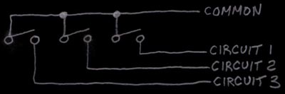
Electrically speaking, a 3-button garage door remote will look like this image, with one common "input" and three unique "outputs." Your choice of which button to push determines which circuit is closed, based on the switch located directly under that button.
When you mount a pushbutton on your bike and a switch to select which remote button you're operating, the circuit will look like this.
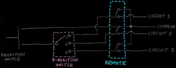
You can see from this circuit that you will need three wires running from the remote to the switch, one wire from the remote to the pushbutton, and one wire from the switch to the pushbutton. You can accomplish this by using a individual wires, but this may look a bit ugly. What I have listed in the table below is a 4-conductor cable, which will clean up the installation.
| Quantity | Item | Part # | Source | Price |
| 1 | Genie Intellicode 3-Button Keychain Remote | GIM-3BL | AAA Remotes | $22.75 |
| 1 | Unshielded, 22 AWG, 4-Conductor Cable (100' Spool) | W122-100-ND | Digi-Key | $29.66 |
| 1 | Single-Row, 3mm, 4-Position Plug | WM1857-ND | Digi-Key | $0.59 |
| 1 | Single-Row, 3mm, 4-Positon Receptacle | WM1847-ND | Digi-Key | $0.59 |
| 4 | 20-24 AWG, Tin, Female Contacts | WM1837-ND | Digi-Key | $0.65 |
| 4 | 20-24 AWG, Tin, Male Contacts | WM1841-ND | Digi-Key | $0.65 |
| 1 | Single-Pole, Triple-Throw Miniature Toggle Switch | 360-1062-ND | Digi-Key | $9.00 |
| 1 | Momentary Pushbutton Switch | CKN1121-ND | Digi-Key | $5.37 |
The first thing you may have noticed about the parts list above is that I have specified a 100' roll of the 4-conductor cable. Obviously, if you have issues with purchasing a $30 spool of cable, you may want to look into finding some loose conductors or a spare section of 4-conductor cable at a scrap yard or friend's garage. If you're in the Phoenix area or don't mind paying for shipping, I'll gladly send you a small section of my spool if you contact me.
To begin the operation, you'll need to crack open your remote and solder wires to the terminals of the buttons. I added a 4-position connector to my remote so that it can be unplugged from the bike in the event that I temporarily need the remote elsewhere. As you solder the wires to the board in your remote, you need to make note of which wires are connected to which buttons. In the picture below, the red wire has been soldered to the "common" side of all three switches. You can see a path on the circuit board that ties together the three common sides of the switches. The path travels from the point where the red wire is soldered to the right, where it connects to the left side of the button #2, then down to the left side of button #3. The three remaining wires are the "other" sides of all three buttons. The green wire is the other side of button #1, the white wire is the other side of button #2, and the black wire is the other side of button #3. If you can't easily inspect your remote and identify these locations, you can verify them with a multimeter. If either of these tasks are beyond your abilities, I would suggest asking a friend who is experienced with electrical or automotive projects to assist in this job.
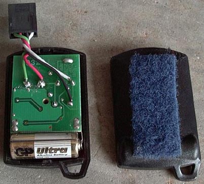
You'll notice that I used a strip of Velcro on the back side of the remote. This allowed me to mount the remote in the tail section of my bike, while still allowing me to unplug the remote without having to remove any hardware. I did not list any mounting hardware in the parts list. The location and mounting style is purely up to you.
Once the remote has been wired, the connector has been added, and you have identified a spot to mount the remote, you need to decide where you are going to mount the switch (if you're going to need one) and the pushbutton. In my case, the pushbutton is located on the left bar just above the high/low beam switch. My button selection three-position switch was located in the hole of the left side fairing.
Once you have selected your locations, cut a length of the 4-conductor cable and route it from your remote to your switch. If you're not using a switch, you're obviously wiring in a 1-button remote and you can just route the cable directly to your pushbutton. Be sure to leave a little extra slack on each end so you have room to work on the remote and the switch or pushbutton. You can always pull the slack out and "hide" it later. In my case, I installed the remote in the "trunk" of my tail section and routed the cable down the frame rails inside the fairings, under the tank, and around the engine to the switch on the left side of the bike. At this point, you can attach a mating connector to the remote side of the cable. At the switch side, you will solder the 3 "non-common" wires to the three "non-common" spots on the switch. If you're using the switch I identified in the parts list, here are some details on it:

Align the switch such that the "NEW P/N M-2024" label is at the bottom. If you're looking at the terminals on the back of the switch with this label on the bottom, the pin numbers will be located as shown above. In addition to the wire connections, you will also need to take a small piece of scrap wire and jumper pins 3 and 5 together on this switch. If you use a different type of switch, this will not apply.
In my case, the green, white and black wires were soldered to pins 1, 4 and 6. After these three wires have been soldered to the switch, you'll need to run another cable from the switch to the pushbutton mounted somewhere on your bike. You'll notice that at this point, the red (common) wire is not connected at the switch. You can now splice this red wire to one of the wires leading to your pushbutton. At the pushbutton end, this wire can be soldered to either side of the pushbutton. Select another wire from the cable and solder it to the other side of the pushbutton. At the switch end, this same wire should be soldered to the "common in" pin, which in this case is pin 2.
If you're having trouble understanding how this circuit works, here's a simplistic version of it. You have one "common" wire in your remote. In this case, I have a red wire soldered to this common. That red wire is spliced all the way up to your pushbutton. When you press the pushbutton, you complete the circuit to the other pushbutton wire, which then goes to the "common in" pin on your 3-position switch. Based on the location of the switch, it then selects which of the three circuits gets connected to this "common in" wire. The circuit is then completed from the switch back to the remote. You have in effect bypassed the actual buttons on the remote, but have not affected the remote's original operation in any way.
If you have any questions or problems, don't be afraid to contact me. As always, it's hard to describe a project like this with text and a few still photos. Good luck!